Effective diagram tools for agentic enterprise architecture
AI agents generate enterprise architecture content at a rate no diagram toolchain can keep up with. In Agentic Executable EA, agents produce capability maps, application landscapes, data-flow diagrams, and transition waves across TOGAF ADM phases and OAA and OMG’s UML. The bottleneck was never the diagram models. It was serving two audiences, humans and agents: a human architect who needs to review, challenge, and present the result, and an agent that must parse the structured source to generate scaffolding and execution plans.
We tested five headless diagram tools against one requirement: an agent emits text, and a standards-compliant diagram comes out the other side. Can the diagram survive a compliance review so agents can implement it to code?
The requirement
This post shows the five diagram types an agent-driven EA pipeline actually emits, all rendered headless from text source to visual diagram before code scaffolding. An agent-driven diagram pipeline has three hard constraints:
- Text in, diagram out: the agent writes a text description; the renderer produces the diagram. No GUI, no drag and drop, no browser.
- Standard semantics: two standards matter. The Open Group’s ArchiMate spec defines element categories (Business, Application, Technology, Motivation, Strategy, Physical) and relationship types (Serving, Realization, Specialization, Composition, Association, Flow, Access, Aggregation, Influence, Triggering). OMG UML (class, sequence, activity, component, deployment) defines the structural and behavioural diagrams that agents need to document application interfaces, message flows, and runtime topology. The renderer must honor both, not just draw boxes.
- Headless, CI friendly: it must run in a Docker container, a GitHub Action, or a subagent terminal session. No Java display server, no Electron, no browser.
Most diagram tools fail one of these three. ArchiMate compliance is the one almost all of them fail; UML coverage is the one that quietly disqualifies the ArchiMate-only tools. Archi and Archify only speak ArchiMate, so an interface sequence or a component deployment model has to be produced by something else. A pipeline where two different tools each emit half the required diagram set breaks at the hand-off.
The audience has shifted
For decades, architecture diagrams were human artifacts: rendered for a slide, read by a person, interpreted in a review meeting. That is no longer the full picture. In agent-driven pipelines, the diagram’s audience now includes implementation agents that parse the model to generate scaffolding, configure infrastructure, validate capability mappings, and emit migration waves. They do not look at a rendered PNG. They read the structured source.
This is why the choice of PlantUML ArchiMate is not just about headless rendering. It is about balancing two competing demands:
- Accurate structure and semantics for AI agents: the ArchiMate stereotypes, relationship macros, and layer color coding encode Open Group semantics; the UML stereotypes and multiplicity syntax encode OMG UML semantics. An LLM can read, reason over, and use both as ground truth when generating downstream artifacts. The diagram’s source is not just text; it is a standards-constrained representation that carries the meaning of a business process, an application service, a data store, and an interface sequence, each distinct from the others.
- Faithful visualisation for humans: the same source renders to SVG/PNG with correct ArchiMate shape sets, relationship glyphs, and layer colors, so a human architect can still review, challenge, and present the model without a separate visual toolchain.
Most diagram tools optimise for one audience or the other. Archi optimises for human visual modelling. Archify optimises for human presentation. PlantUML ArchiMate is the tool I found that serves both: the text is the primary artifact, the image is a projection of it, and neither audience is an afterthought.
What I evaluated
| Tool | Text in / Text out | ArchiMate semantics | OMG UML semantics | Headless / CI | Verdict |
|---|---|---|---|---|---|
| Mermaid | Yes | None | Partial | Yes | No |
| D2 | Yes | None | None | Yes | No |
| Archi (Archi-mcp) | Yes | Yes | None | Partial | No |
| Archify | Yes | Minimal | None | Yes | No |
| PlantUML ArchiMate | Yes | Yes | Yes | Yes | Yes |
Mermaid
Mermaid is the default for process maps, journey charts, and sequence diagrams in Obsidian. I use it daily for workflow paths and ADM state transitions.
What it lacks: ArchiMate has no place in its shape library. A “capability” and an “application component” render as the same box. There is no <<business-process>> stereotype, no ArchiMate relationship glyph, no layer color coding. You can approximate the notation with labels and shapes, but the moment a standards-compliant output is required, a TOGAF Phase B capability model for example, Mermaid is the wrong tool.
UML is the same story: Mermaid’s class, sequence, and state diagrams are approximations, not OMG UML. No multiplicity syntax that maps to UML semantics, no component or deployment diagram type, no profile stereotypes. Fine for a workflow sketch; not a standard-compliant UML artefact.
I use Mermaid where it is strong. ArchiMate is not that place.
D2
D2 is a text-to-diagram engine with clean syntax and an MCP server (d2mcp). I was initially recommended to pair it with archimate-mcp for headless ArchiMate rendering.
The problem: D2 is a generic graph layout engine. It has no ArchiMate shape set. No cylinders for data stores, no hexagons for capabilities, no ArchiMate relationship arrows. There is no D2 extension, shape library, or sprite set in the ecosystem that adds ArchiMate notation. UML is the same: no class, sequence, component, or deployment diagram types. D2 draws generic nodes and edges, whatever the label says. You end up faking it with labels and custom shapes, which defeats the purpose of standards-compliant output.
D2 also had a practical rendering issue: grid layout renders a literal node labeled “grid” instead of applying grid layout. You have to use direction: right or switch to engine: elk. A pitfall that cost debugging time.
D2 is a good diagram engine. It is not an ArchiMate renderer.
Archi (ArchiGPT)
Archi is the de facto open-source ArchiMate modeling tool. ArchiGPT is an LLM plugin that can generate Archi XML from text. This is where it gets interesting and where it breaks.
The generation side works: the LLM produces valid Archi XML that Archi can open. But the visualisation side requires human intervention. The Archi GUI is an Eclipse/SWT application. The embedded MCP server (fanievh/archi-mcp-server) serves only the currently open model, requires Archi to be running with a display, and queues mutations behind an approval gate. For agent-driven, headless pipelines, a CI job that emits a diagram, a subagent that renders a capability map, this is a dealbreaker.
And Archi speaks ArchiMate and only ArchiMate: no UML. An agent that produces a TOGAF Phase C application architecture also needs interface sequence and component deployment models, and Archi cannot produce either.
Archi is the best tool for human-in-the-loop ArchiMate work. It is the wrong tool for agent-driven rendering.
The headless alternative (thijs-hakkenberg/archimate-mcp, pure npx, coArchi2 XML) solves the CI problem but adds a dependency and a model format to maintain.
Archify
Archify produces polished, animated HTML diagrams with a dark semantic color palette. The visual quality is high. The animation is the point.
The problem: ArchiMate standards are not baked in. Archify’s design system is its own semantic color palette (cyan=frontend, emerald=backend, violet=database). ArchiMate layer color coding, the Open Group’s Business/Application/Technology/Motivation/Strategy/Physical/Implementation color scheme, is not represented. UML is entirely absent too: no class, sequence, or component diagrams. Its output is a presentation format, not a modelling format. The output looks great in a pitch deck. It is not standards-compliant ArchiMate or UML.
For a pitch slide, Archify wins. For an architecture repository artifact that must survive a TOGAF compliance review, it does not.
Why PlantUML ArchiMate
PlantUML ships ArchiMate as a native diagram type. The PlantUML ArchiMate spec supports:
- The
archimatekeyword for element definitions - Stereotypes that map to ArchiMate icons (
<<process>>,<<data-store>>,<<business-process>>,<<application-service>>) - Layer color coding via
#Business,#Application,#Technology,#Motivation,#Strategy,#Physical,#Implementation - A standard library with ArchiMate macros:
Category_ElementName()for elements andRel_RelationType()for relationships
UML is the other half of the requirement, and it is why PlantUML is the only tool in this comparison that clears both bars. PlantUML is the reference implementation for UML in text form: class, sequence, activity, use case, component, and deployment diagrams are first-class, native syntax, not an extension or a sprite set bolted on. The same jar, the same CI step, the same .puml source format renders an ArchiMate capability map and the UML sequence diagram of the interfaces that capability exposes. An agent emits one text stream; compliance with both standards comes out the other end. That is what no ArchiMate-only tool can do: Archi and Archify stop at ArchiMate, so the UML half of the artefact set, interface sequences, component and deployment models, has to be produced by a second tool, which is where the pipeline breaks at the hand-off.
The relationship macros cover all the ArchiMate relationship types agents need: Access, Aggregation, Assignment, Association, Composition, Flow, Influence, Realization, Serving, Specialization, Triggering. Direction modifiers (_Up, _Down, _Left, _Right) give layout control without fighting the auto-layout engine.
The rendering step is a single Java jar:
java -jar plantuml.jar archimate-model.puml
# Outputs: archimate-model.png, .svg, .pdf
No display server. No GUI. No model file to open. The agent writes .puml, the jar renders the image. In a CI pipeline, the agent emits the text file; a step renders it to SVG and commits both. The .puml source is diff-able, version-controlled, and re-renderable.
The one pitfall: the community plantuml-archimate sprite examples use <<$archimate/...>> syntax that is stale for the current jar. The working form is bare stereotypes like <<process>> and <<data-store>>. Once you know that, the syntax is straightforward.
The minimal working example, one capability realizing one application estate, native ArchiMate icons from the jar’s built-in sprite set:
@startarchimate
Capability "Customer service" <<capability>> as cs cap
ApplicationComponent "MeridianCore" <<application-component>> as mc

cs --r-> mc : realizes
@endarchimate
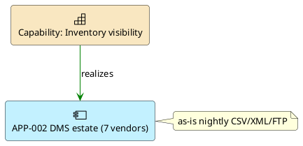
PlantUML source: sample.plantuml
That minimal example is the unit. The two samples below are what a real agent-driven pipeline emits with it, all headless, all from .puml source.
Sample 1. Capability-to-application mapping
The TOGAF Phase B artefact, mapped to Phase C. L2 capabilities (ArchiMate Strategy layer, native capability icons) realize as-is application estates, which push nightly CSV/XML/FTP into a 480-module monolith. Dashed edges are the planned event-bus contracts; the gap note carries the quantified leakage.
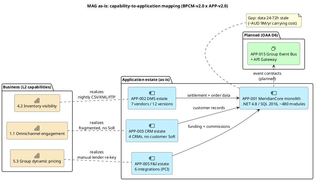
PlantUML source: mapping.plantuml
Sample 2. Transition waves with governance gates
The Phase F / OAA transition plan: three waves, each gated by an ARB + security checkpoint before the next wave progresses. Course-of-action icons per wave, implementation-event gates, and a gap-filled terminal state where the monolith is retired.
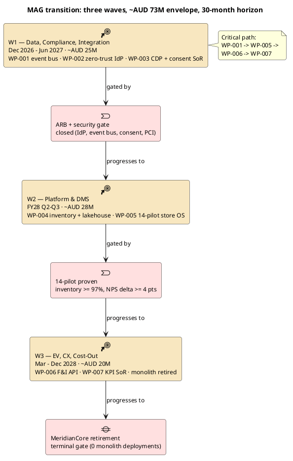
PlantUML source: roadmap.plantuml
Sample 3. The pipeline itself
The full loop: agent emits .puml, the jar renders, both artifacts land in version control. The note is the thesis, one artifact, two audiences.
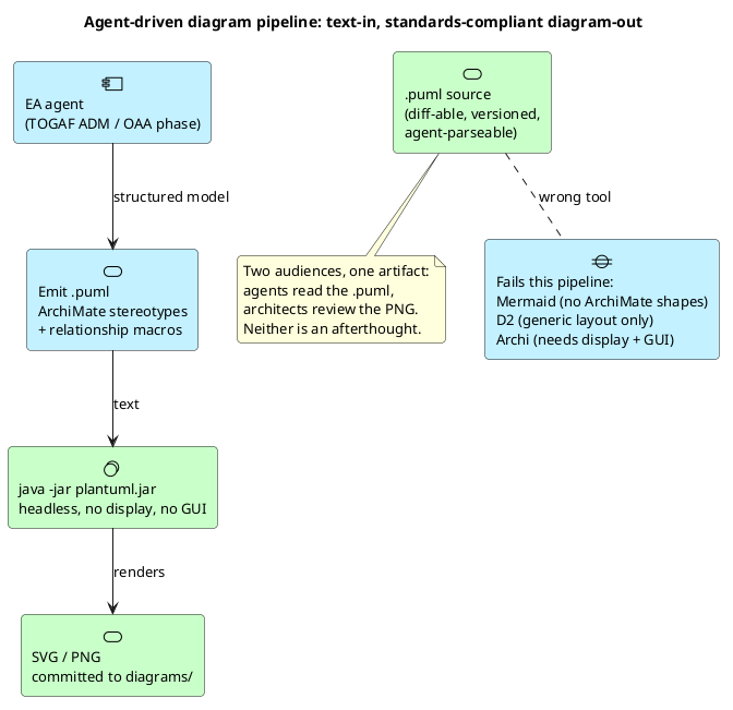
PlantUML source: pipeline.plantuml
What the alternatives look like on the same content
The TOGAF ADM cycle with an OAA feedback loop, drawn in Mermaid. Eight ADM phases in a left-to-right chain; OAA sits above, feeding back into Phase B. Clean layout, zero ArchiMate notation: every box is just a box.
flowchart TB
    L["Continuous discovery"] --> M["Architecture as code"]
    M -. "continuous evolution" .-> B
    G -. "feedback" .-> L

    subgraph ADM["TOGAF ADM cycle"]
        direction LR
        A["Vision"] --> B["Business"] --> C["Info Systems"] --> D["Technology"]
        D --> E["Opp. & Solutions"] --> F["Migration Planning"] --> G["Impl. Governance"] --> H["Arch. Change Mgmt"]
        H -. "feeds back to Vision" .-> A
    end
Source: mermaid-sample.mmd
Same pipeline, now drawn in D2. Vertical chain: one node per row, no subgroups; the data store faked as a cylinder. Still no ArchiMate shape set. The shapes are generic.
# MarsEV: the diagram pipeline as a generic system diagram (D2)
# Deliberate vertical chain: no subgroups, one node per row.
direction: down

agent: "Agent (LLM)
emits .puml / .d2 / .mmd"

texts: "Text files (*.plantuml, *.d2, *.mmd)
diff-able, CI-friendly"

render: "Headless renderers
java -jar plantuml.jar
d2 -o out.png in.d2
mmdc -i in.mmd -o out.png"

out: "diagrams/ + source in git" {
  shape: cylinder
}

agent -> texts: "structured text"
texts -> render: "CI step"
render -> out: "commit both"
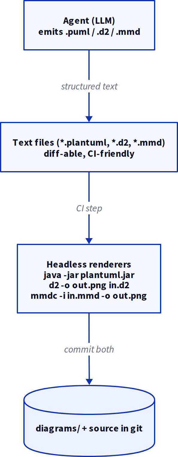
Source: d2-sample.d2
The pipeline that works
flowchart TB
    A["Agent writes ArchiMate model<br/><i>structured data or natural language</i>"] --> B["Agent emits .plantuml file<br/><i>ArchiMate stereotypes + relationship macros</i>"]
    B --> C["java -jar plantuml.jar *.puml<br/><i>headless render</i>"]
    C --> D["SVG / PNG lands in diagrams/<br/><i>committed alongside the .puml source</i>"]
    B -.- E["Archi opens the underlying<br/>ArchiMate model for human review"]
    B -.- F["Open Group XML export<br/>for tools that require it"]
    E --- F
    linkStyle 3 stroke-dasharray, stroke:#666
    linkStyle 4 stroke-dasharray, stroke:#666
    linkStyle 5 stroke-dasharray, stroke:#666
Source: pipeline-work.mmd
The .plantuml file is the durable interchange format. It is text, it is diff-able, and it re-renders deterministically. Archi can open the underlying ArchiMate model for human review if needed. The Open Group XML export can be generated separately for tools that require it.
What this means for agent-driven EA
The gap in EA tooling is not the modeling language. It is the rendering layer between an agent’s output and a standards-compliant diagram. PlantUML ArchiMate is the first tool I tested that treats the diagram as text, renders it headlessly, and bakes in both the Open Group’s ArchiMate and OMG’s UML standards natively. One tool, one source format, two standards’ worth of compliance.
For teams building agentic EA pipelines on TOGAF, OAA, or custom ADM workflows: use Mermaid for process maps, D2 for generic system diagrams, and PlantUML ArchiMate for anything that must be standards-compliant ArchiMate or UML. The tooling decision comes down to one question: does the diagram need to survive a compliance review? If yes, PlantUML. If no, anything else works.
Have you shipped an agent-driven ArchiMate pipeline, or are you still fighting the rendering layer?